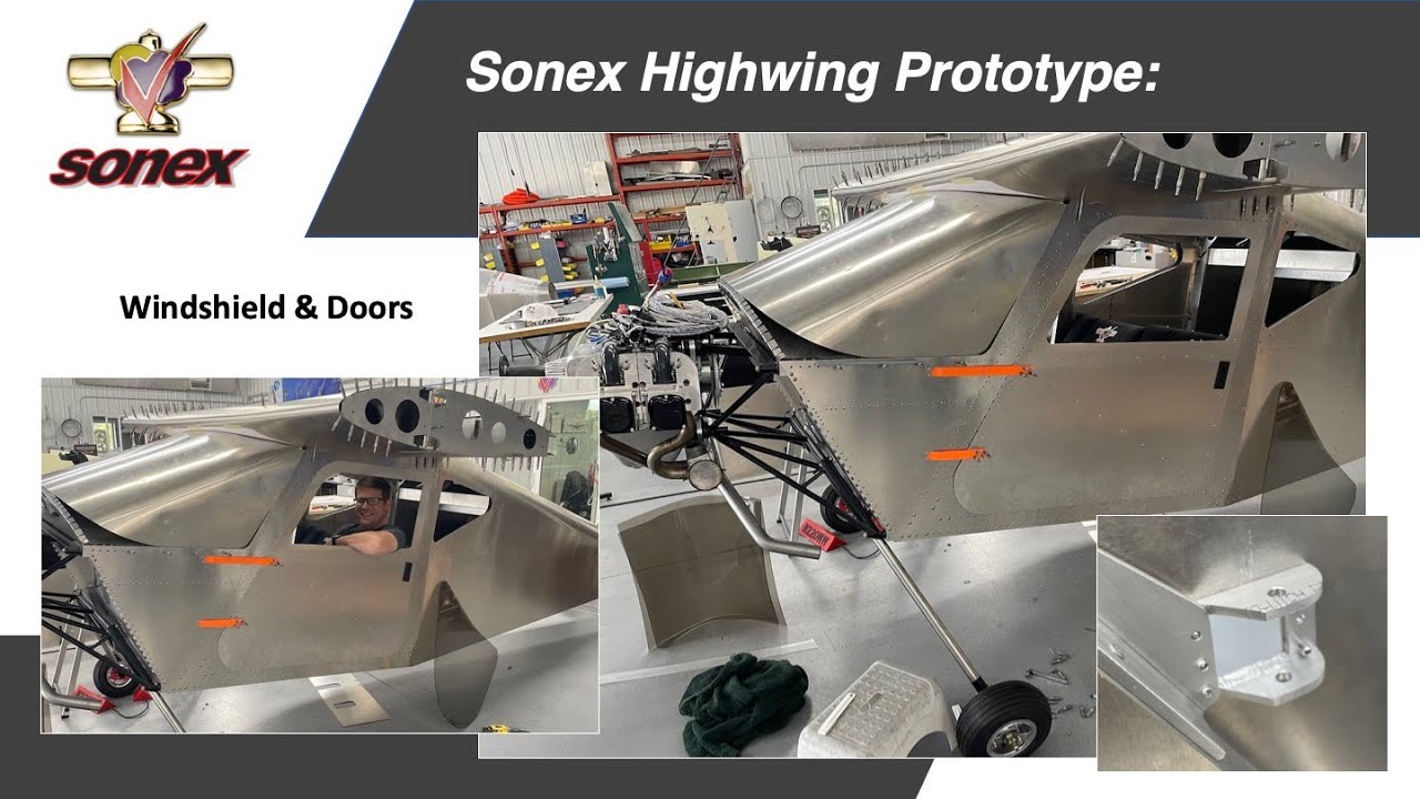
Sonex has been hard at-work with construction of the new Sonex Highwing prototype, and a summary of our progress was presented during a live webinar during EAA Homebuilders Week last Thursday by Sonex Owner & President and Sonex Highwing designer Mark Schaible. A video archive of the presentation can be viewed above, and on our YouTube Channel. Don’t forget to subscribe to the Sonex Highwing Mailing List to automatically receive future updates!
Reserve Your Place in Line for a Highwing!
We have received many requests from prospective Sonex Highwing builders to be able to place a deposit and reserve their place in line for a kit. We are excited to announce that as-of this posting, you may place a $500 Kit Reservation Deposit. These deposits not-only get you a place in line amongst your fellow future Highwing builders, but also helps Sonex to plan for kit inventory needs. Kit Reservation Deposit Holders will be given the opportunity to turn their reservations into firm orders following the first flight tests of the prototype aircraft. Deposits are refundable minus a $50 cancellation fee. If you have any questions, please reach-out to us via our Contact Form.
When Will it Fly?
We are working hard to fly the first Highwing prototype as-early as possible this Spring. While there are no guarantees, our estimate for first flight is April of this year, possibly even late March. The first prototype is in tailwheel configuration powered by a UL Power UL350iS engine. Following flight test of the first prototype, a tricycle gear prototype will also be constructed. Here is the progress since our last project update:
|
Deposits are refundable less a $50 Cancellation Fee. |
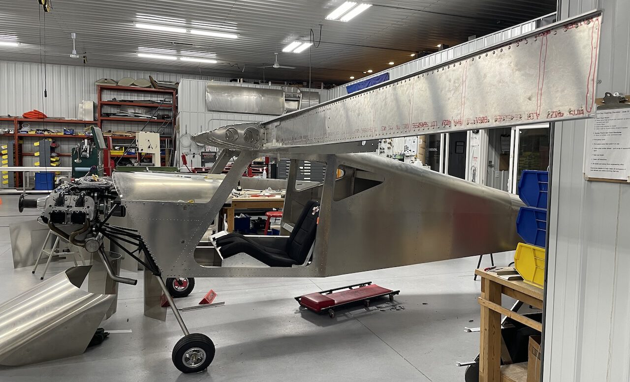
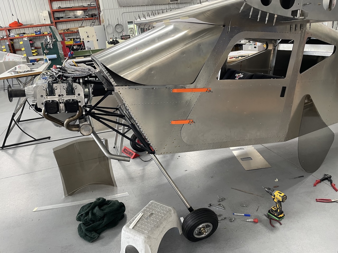 Sonex Highwing prototype with first-article doors, 3D printed test hinges (final hinges will be machined aluminum), and windshield mockup with UL350iS engine hung on the mount.
Windshield and Doors
A windshield mockup was fitted to the Highwing prototype to finalize the windshield shape and begin the process of building tooling for production of windshields. This metal mockup not-only served as a useful tool for confirming trim lines and bend radius for the plexiglass, but also gave us the first glimpse of the attractive lines of the Sonex Highwing, which were not as evident when the fuselage was displayed at AirVenture 2024. The metal mockup also spurred a lot of Spirit of St. Louis jokes in our shop accompanied by some great Jimmy Stewart impersonations!
Highwing windshields will be heated and drape-formed on a mold similar to our windshield mockup, yet slightly smaller to accommodate the thickness of the glass along with a protective felt layer on the tooling. Some new tooling for the Sonex canopy oven has been built, consisting of a welding blanket lined shelf and an insulated lid allowing the plexiglass to be heated as a pre-cut shape without the need for any clamping inside the oven. Heating and forming tests of sample material show that the windshield shape will be easily formed and the bend radius in the windshield is distortion free. The final mold will be built soon, and we can begin making windshields.
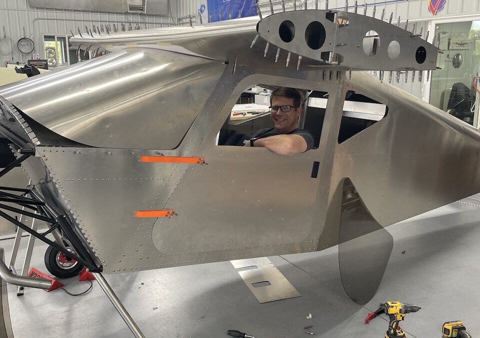 This view shows the first glimpse of the attractive lines of the aircraft with the streamlined windshield joining the center section wing and the tailcone flowing-back from the upper camber of the wing.
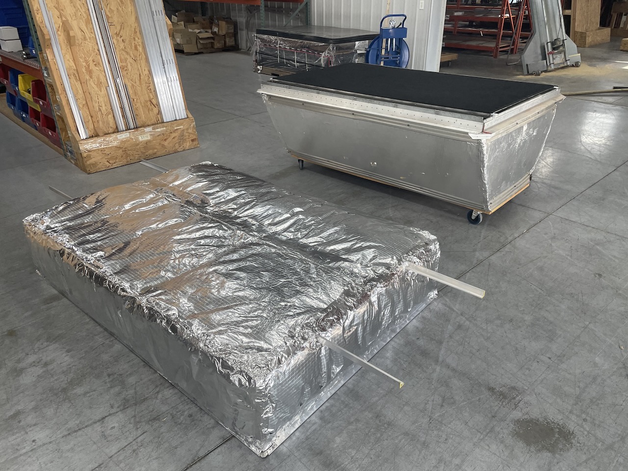 Sonex canopy oven with its new windshield shelf installed and new insulated oven cover laying on the floor in the foreground.
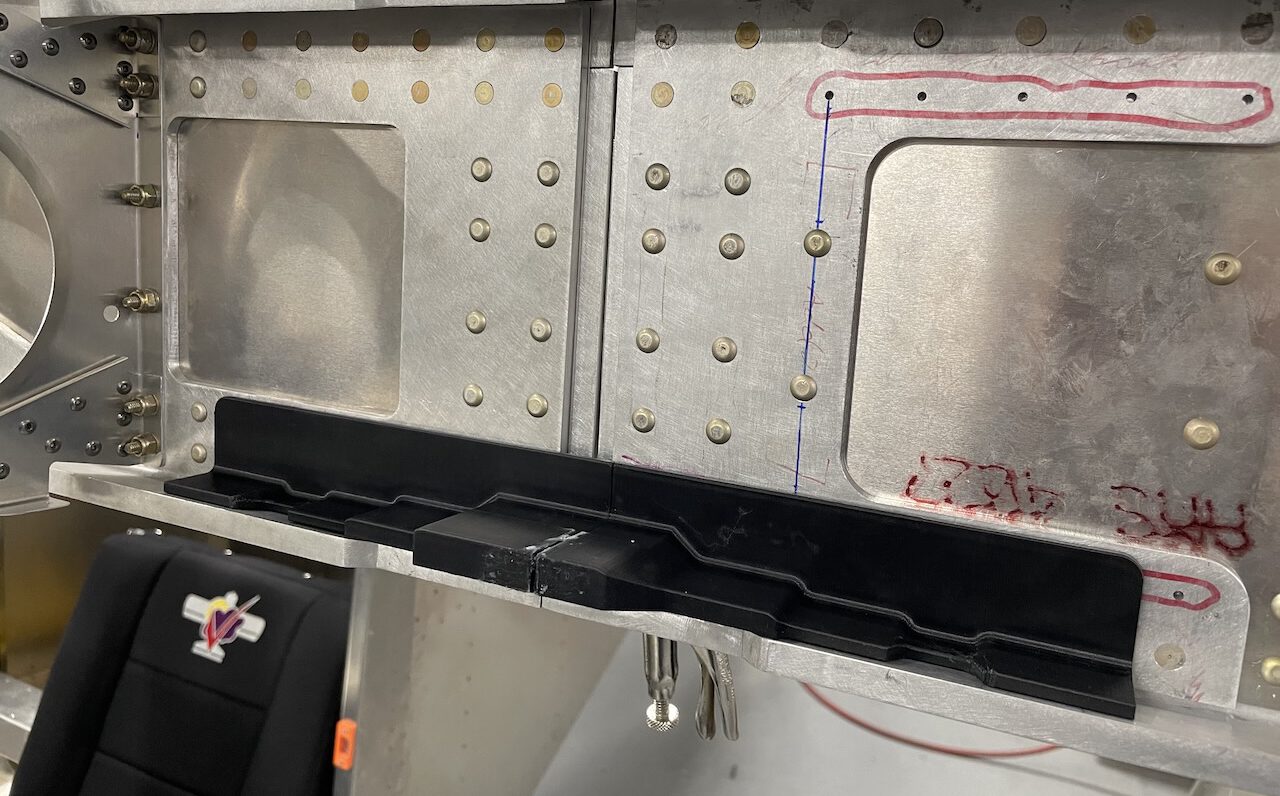
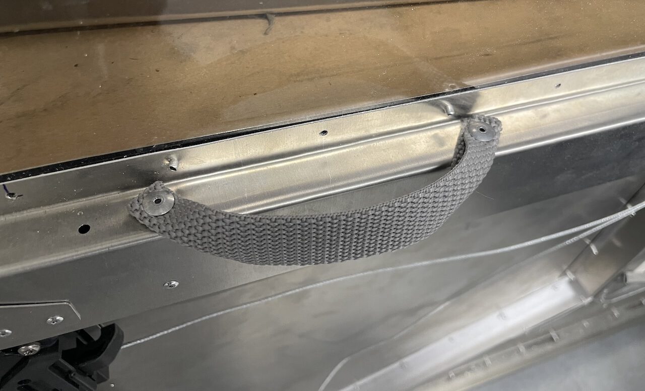 The Highwing door will be closed from the inside via a simple nylon webbing door handle to maximize pilot space and comfort. The door latch can be seen at the bottom-left with the latch release cable run horizontally.
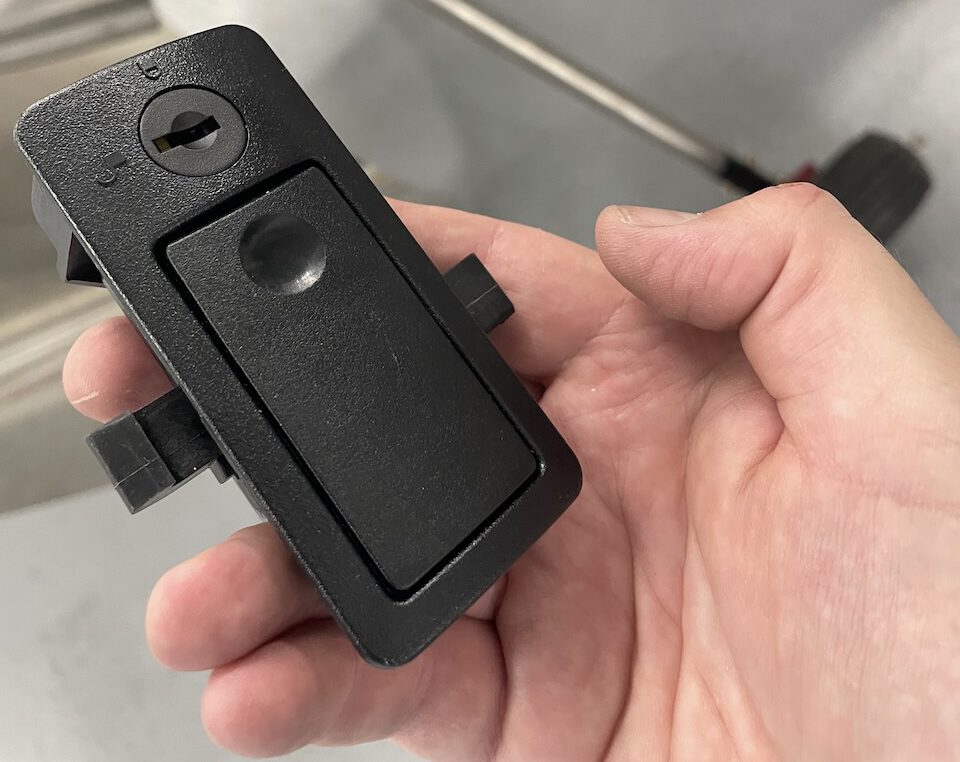 The Highwing door will use a simple flush-mount locking latch assembly from Southco. The latch can be locked from the outside while still allowing children & pets in a hot Walmart parking lot to open the door from inside.
 The door latch is mounted “upside-down” for more ergonomic use of the latch and to prevent moisture from entering the inside of the door frame.
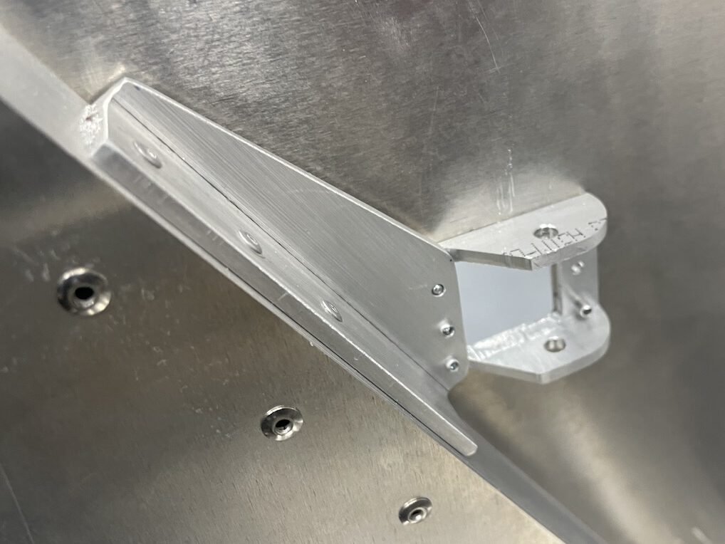 The door hinge hinge pins are inside the forward fuselage to allow easy installation of an aerobatic door jettison cable. Ignore the “bad” temporary rivets and need for deburring shown here – this is just a test piece!
The Highwing door structure has been through a few iterations to achieve the desired stiffness of the door frame, which is shaped to maximize elbow room with no ribs in that area of the door. ABS-molded interior trim panels will be vacuum formed for the inside of the doors and will be concave in the area of the occupant’s elbows to take advantage of the full width of the cabin.
We have selected simple, lightweight and inexpensive flush-mount door latches from Southco. These latches can be locked from the outside with a key, but still opened from the inside when locked. We will be using a simple cable to open the spring-loaded latch pawl. The cable will be attached to a small braided nylon loop exposed through the ABS-molded door trim panel. A nylon webbing strap is also used for the door-close handle, making it easy to grab without being rigid so that it does not encroach upon the occupants inside.
As shown in previous updates, the door hinges will consist of machined aluminum straps to the forward fuselage. The door hinge pins will be located inside the forward fuselage to allow easy installation of an aerobatic door jettison cable. The door has been test-fit and operated using several iterations of the door straps via 3D printed test pieces before finalizing the aluminum hinge design.
Outboard Wings
Outboard main wing spars for the cantilevered Sonex Highwing wings were riveted late last Fall and test fitted to the center wing section using 3D printed test pieces simulating the machined aluminum wing spar attach ties to ensure proper fit of the ties to the interior of the spar caps and the spar web before machining. Wing rib design has been finalized for aileron pushrod clearances and proper spacing to the various main wing spar laminations. Ribs and rear spars have been cut and formed and construction of the outboard wings is currently in-process.
 Outboard wing spars were completed and test fit to inboard spars.
 3D printed samples of the machined aluminum main wing spar ties were test fit to ensure proper fit before machining. The steps in the tie straps allow all wing attach bolts to be loaded equally.
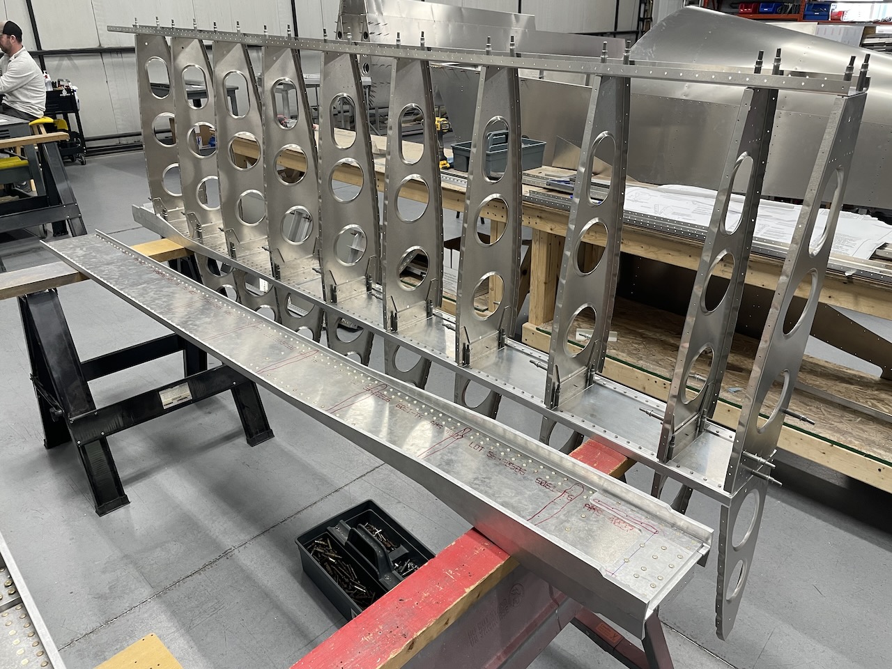 Ribs and rear spar being fitted to the completed outboard main wing spar. The oval lightening holes allow pass-through of the aileron pushrod.
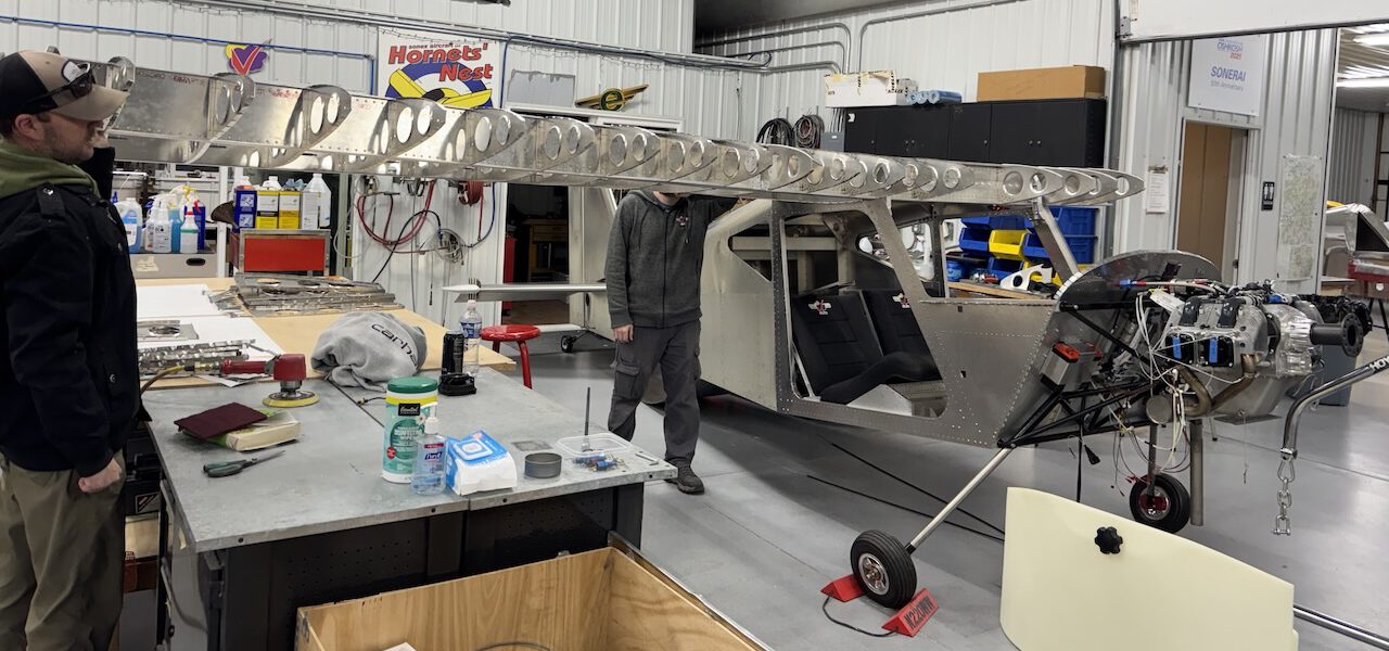 Another test fit of the framed-up outboard wing skeleton to the inboard wing, giving a better sense of the finished aircraft’s span.
Convertible Control Sticks
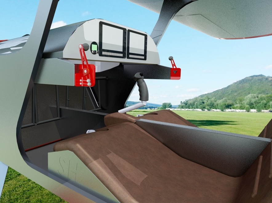
As promised in earlier updates, we are offering control sticks that can easily be interchanged between dual stick and center stick configurations between flights. While the center stick configuration (one control stick in the middle of the cabin to be used as a side stick by the pilot) is the easiest for getting in and out of the cockpit, some pilots insist upon having the traditional stick arrangement between their legs, and most training applications will require the same. A simple control stick attachment method has been devised using widely available threaded cable glands and an indexing pin. A large O-ring under the gland nut allows hand-tightening of the attachment while eliminating all free-play in the installation. The sticks can be un-threaded, removed and re-installed without any tools meaning that pilots can install the control stick between their legs after getting into the aircraft and can remove the stick before getting out.
 Center stick installation.
 Dual stick installation.
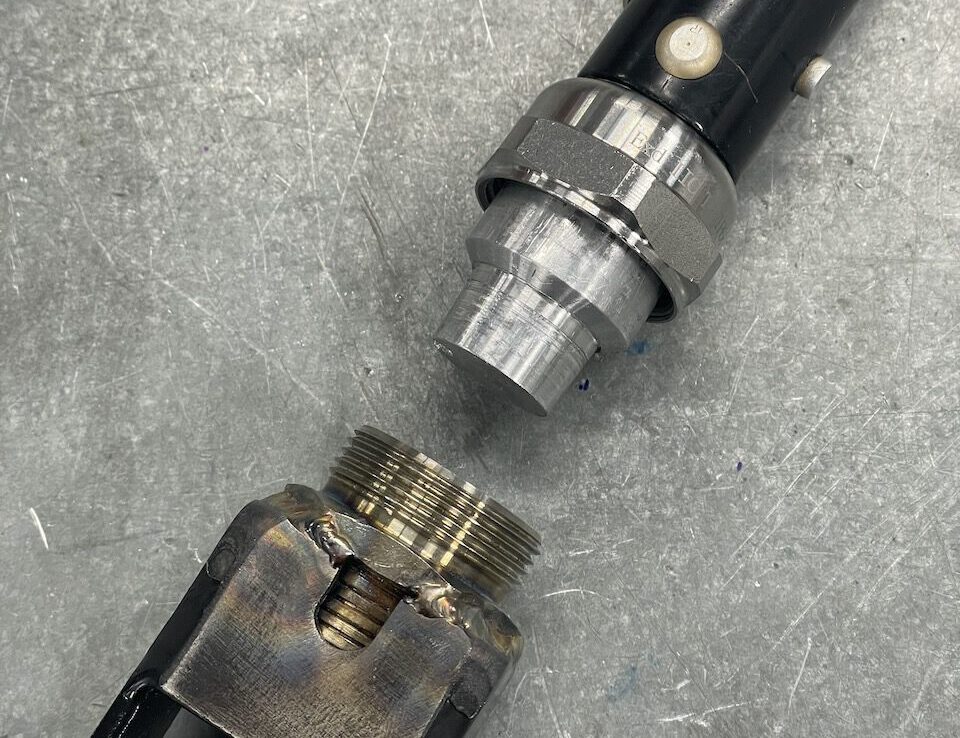 Stick disconnected from aircraft.
 Stick installed to aircraft stick frame.
Ceiling Aileron Controls
Torque tubes in our aileron control systems in the Sonex Highwing and the SubSonex Personal Jet are insulated from torque tube spring effect due to the fact that the aileron pushrods from each wing are directly connected to each other. This along with other design features helps to avoid flutter, even in extremely fast aircraft applications such as the SubSonex.
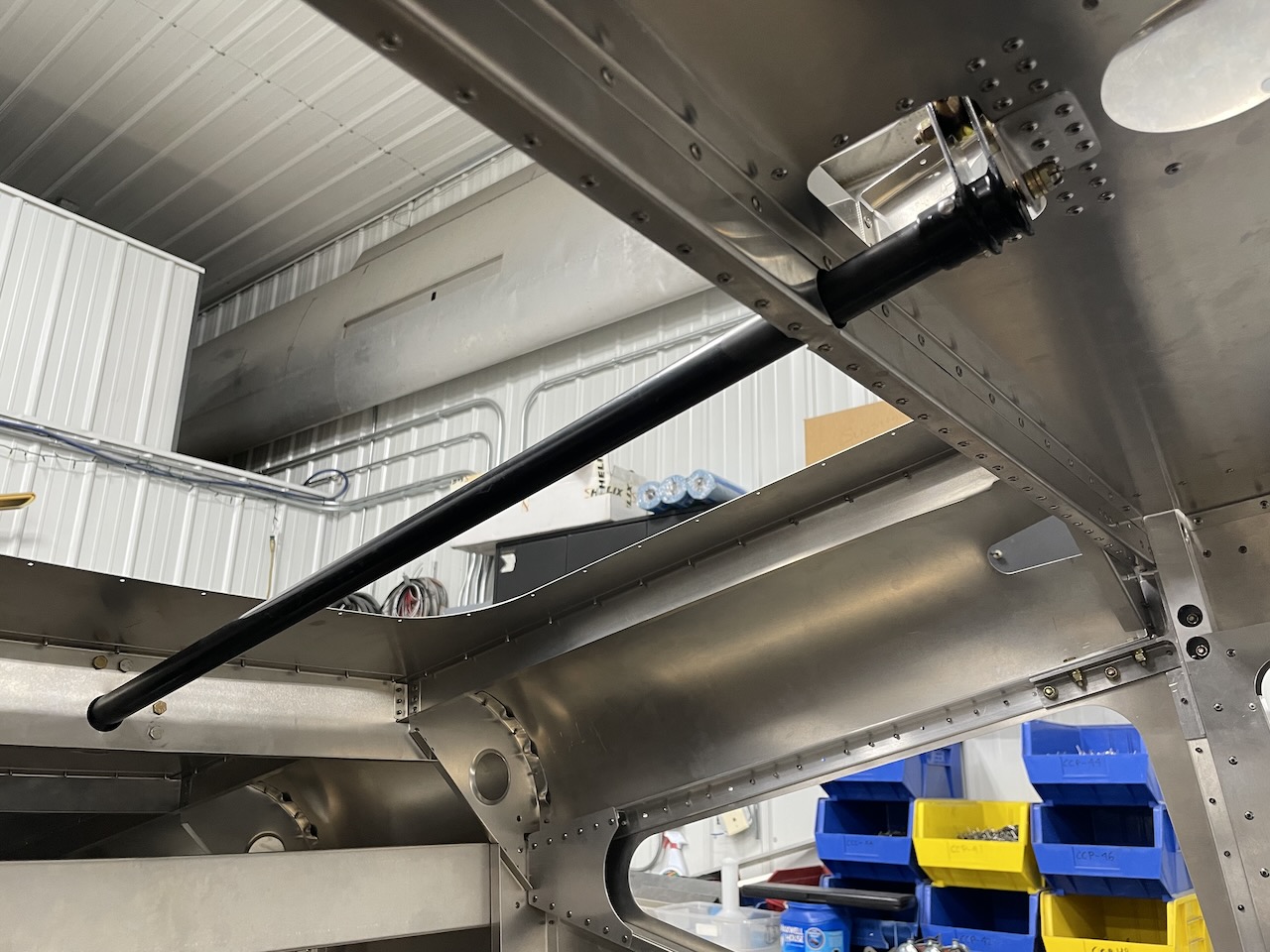 Upper aileron torque tube installation.
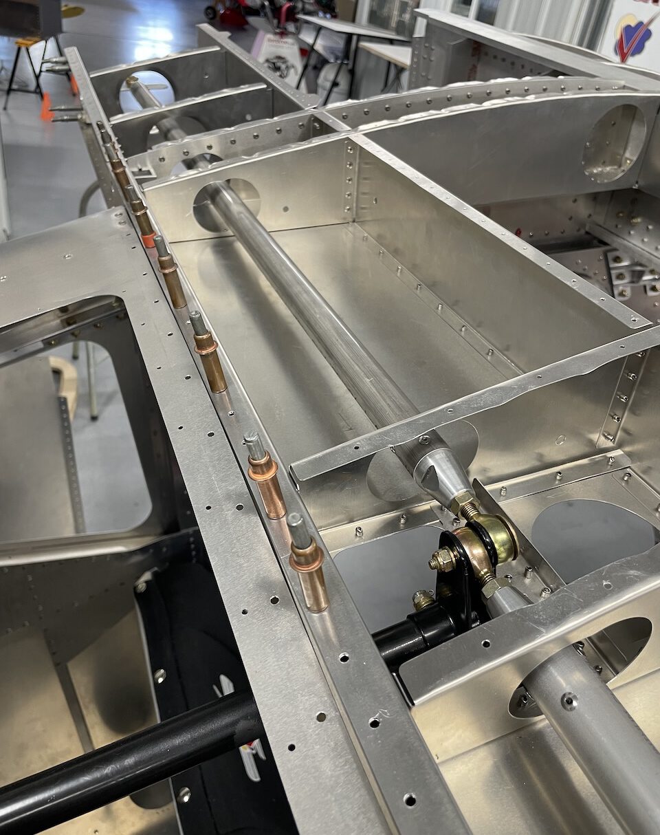 Inboard aileron pushrods connected to upper aileron torque tube.
 Sonex Highwing flight control system layout.
Rudder Cables
 Port and starboard color-coded rudder cable housings.
Rudder Pedals & Brakes
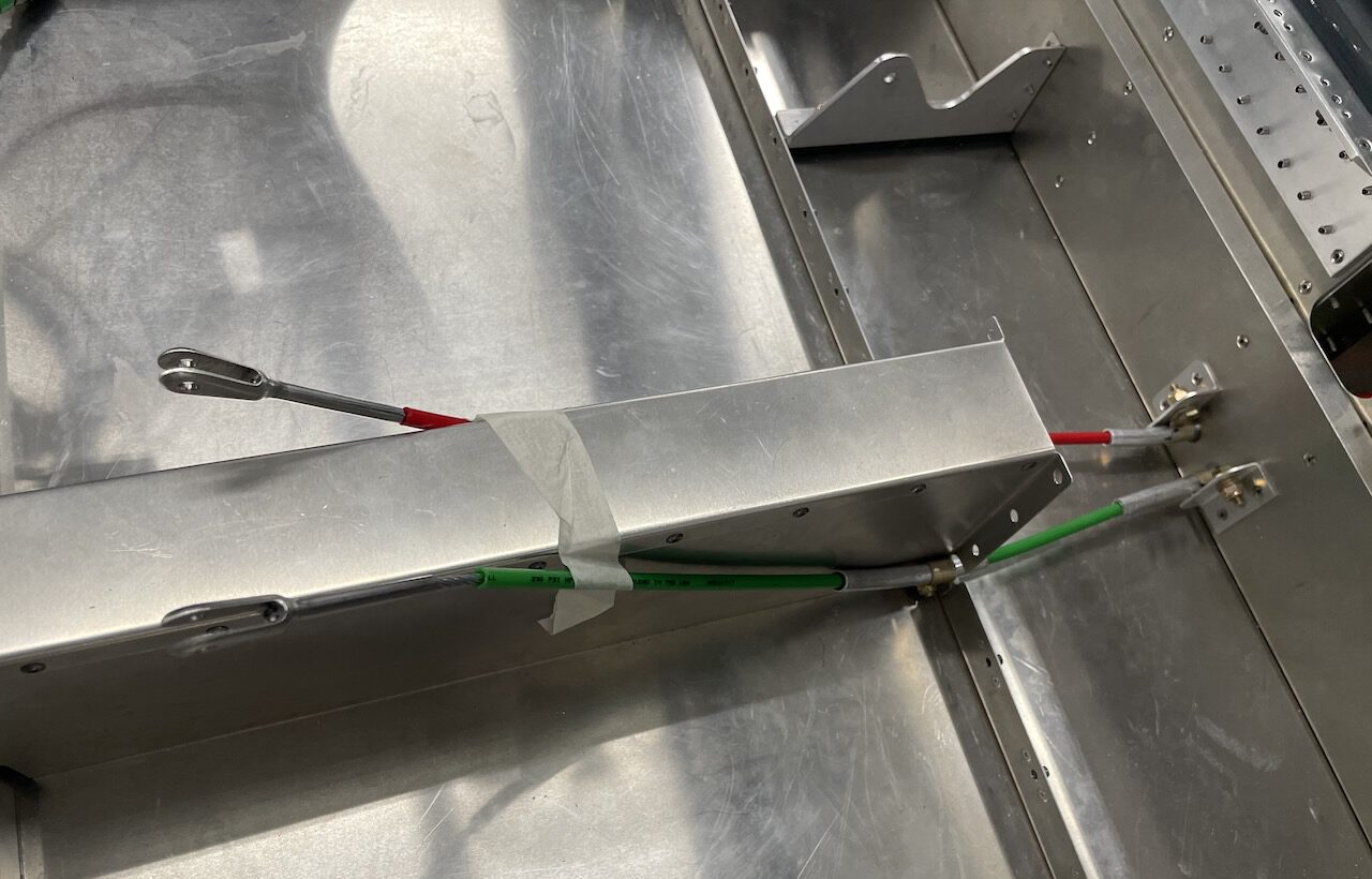
Sonex will be testing toe brakes in the Sonex Highwing, in-conjunction with AeroConversions Aerobrake brake calipers. Toe brakes are not found in other Sonex aircraft designs, as our aircraft feature direct steering of nose wheels and tailwheels, and we prefer the simplicity and low-cost of a universal brake installation with both brakes applied simultaneously via a hand brake lever. Due to its large doors, however, the Sonex Highwing presents unique challenges with regard to brake handle and master cylinder placement, especially if braking access by both pilots is desired in the center control stick configuration. Our prototype toe brake installation is unique in that it requires only one pair of lightweight brake master cylinders on the pilot side rudder pedals. A simple cable system is used to actuate the pilot side master cylinders from the passenger side brake pedals. This installation will reduce both weight and cost.
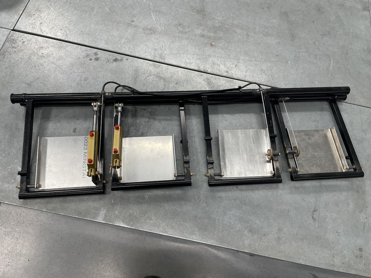 Pilot and passenger side rudder pedals with toe brakes installed.
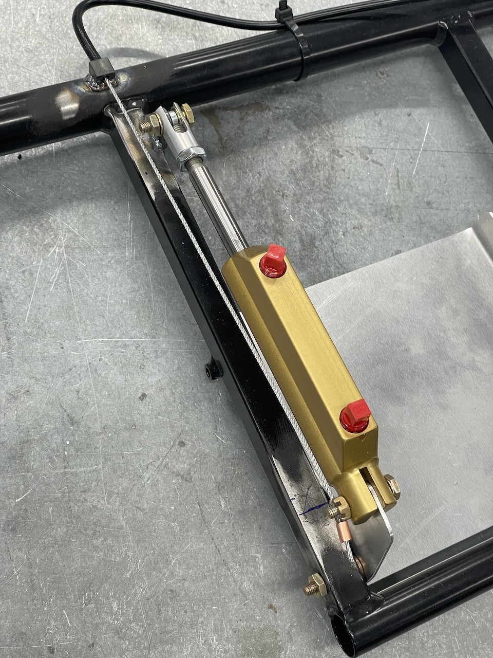 Cable attached to pilot side brake master cylinder.
 Right rudder pedal (right brake) pilot side master cylinder actuated by passenger side brake pedal via cable system.
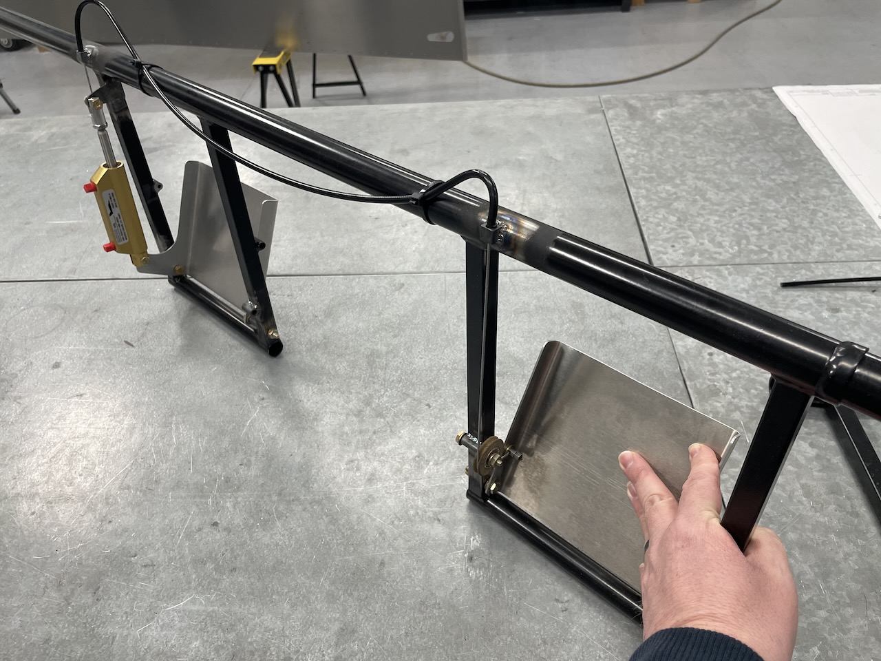
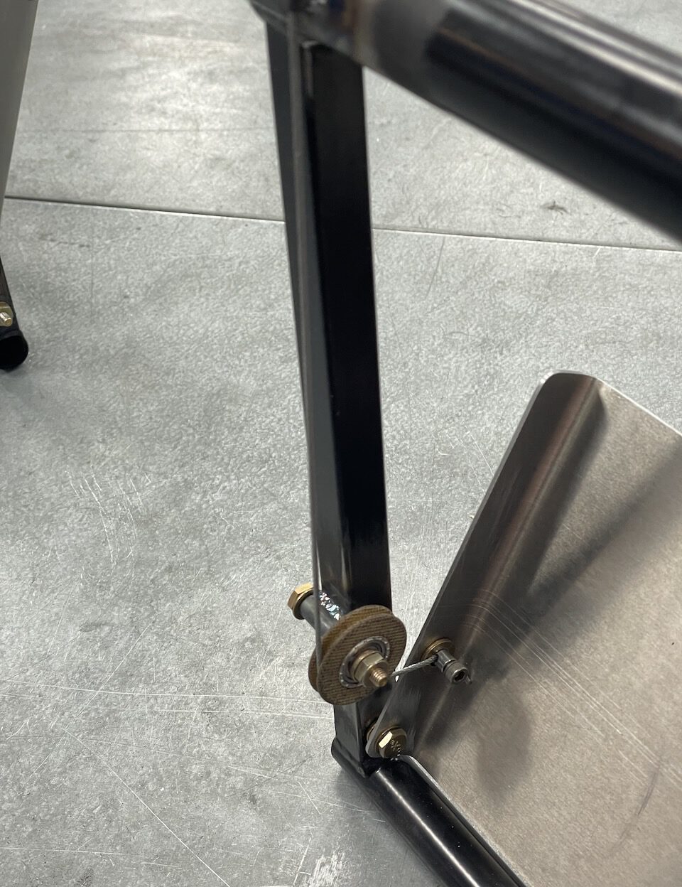 Cable attached to passenger side brake pedal via a pulley. Note that pulleys will get proper pulley cable guards in final installation.
Tail Tips
Seemingly a small item, the fiberglass tail tips for the Sonex Highwing have arrived and have been fit to the empennage. These are the first fiberglass parts that we have made using a 3D printed plug. As a result, tail tips on the Sonex Highwing were extremely easy to fit and install.
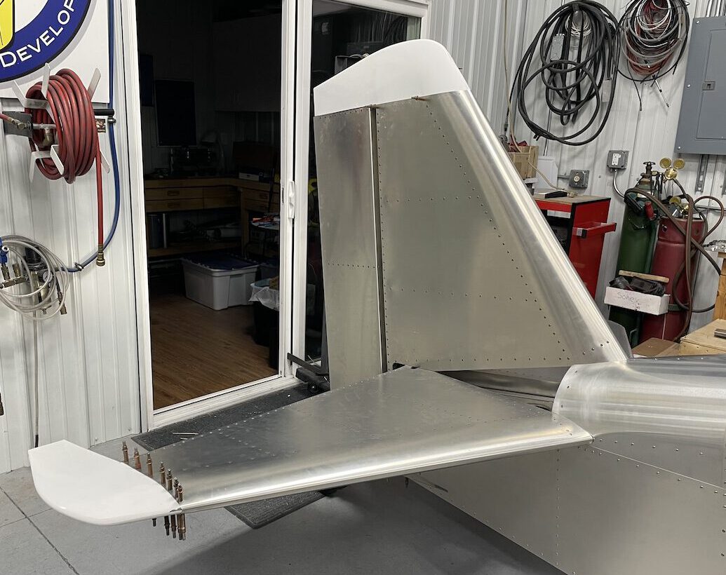 Fiberglass tail tips fitted to the Highwing prototype.
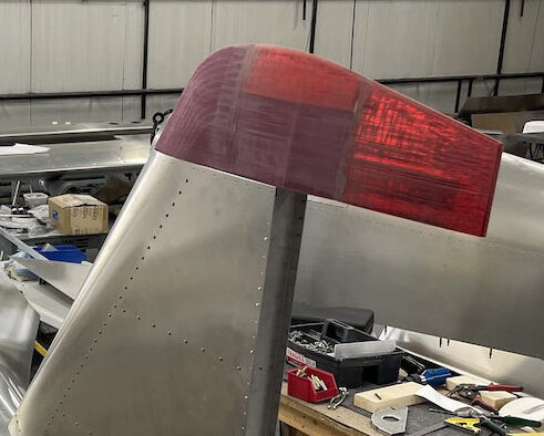 3D printed plugs make the Highwing fiberglass tail tip molds extremely accurate resulting in parts that are easy to fit.
Engine Installation: UL350iS
The 130hp UL Power UL350iS has been hung on the engine mount, and firewall-forward installation work is progressing. We have mounted fuel pumps, ECUs, ignition coils, battery box, voltage regulator, and fine fuel filter mount to the firewall. The ECUs are mounted to the aft side of the firewall to protect against heat. CHT and EGT probes are installed and wiring for those probes and the ECUs is in the process of being routed and tidied up. The battery box has been built to hold an Odyssey PC680 battery and can also use an EarthX battery. Final battery selection will be made as the aircraft’s final weight & balance comes into focus.
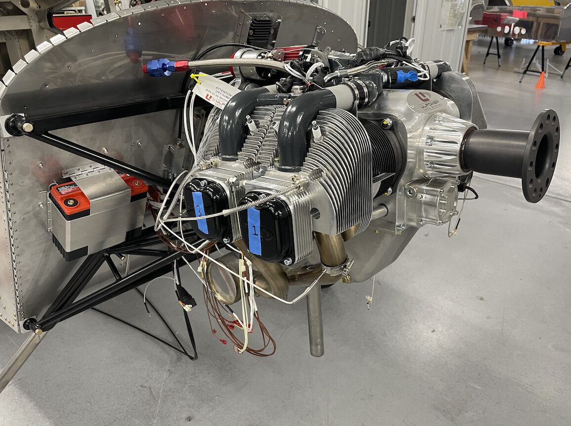 Engine mounted to the firewall with CHT & EGT probes installed. The battery box is also seen here.
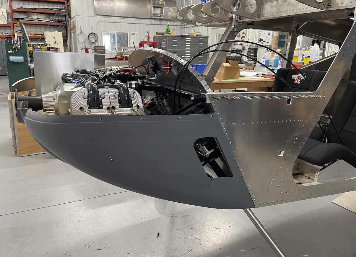 Preliminary cowling fit shows no unexpected interferences with the engine and verifies correct prop hub spacing.
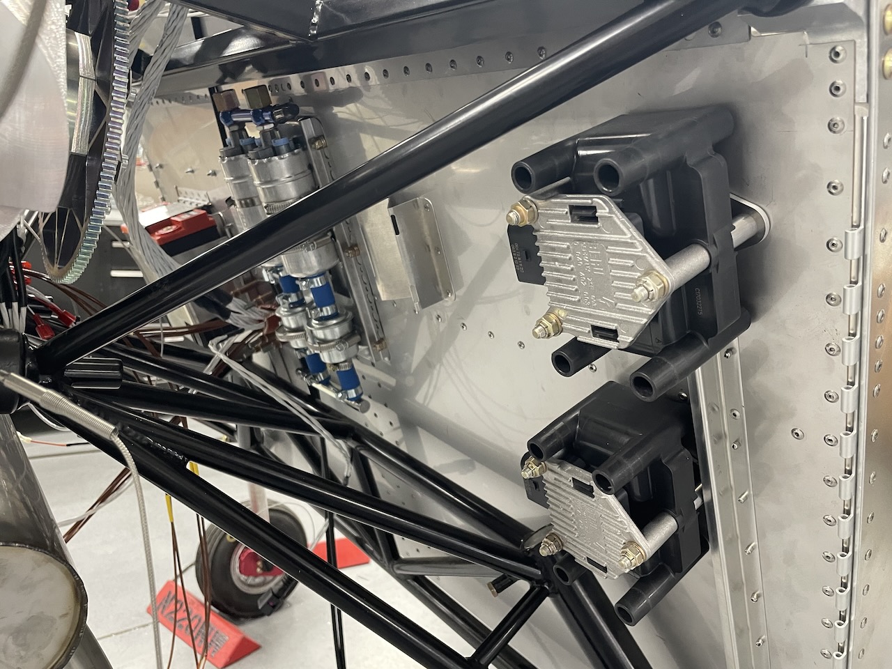 Ignition coils, fine fuel filter mount, fuel pumps and battery box mounted to the firewall.
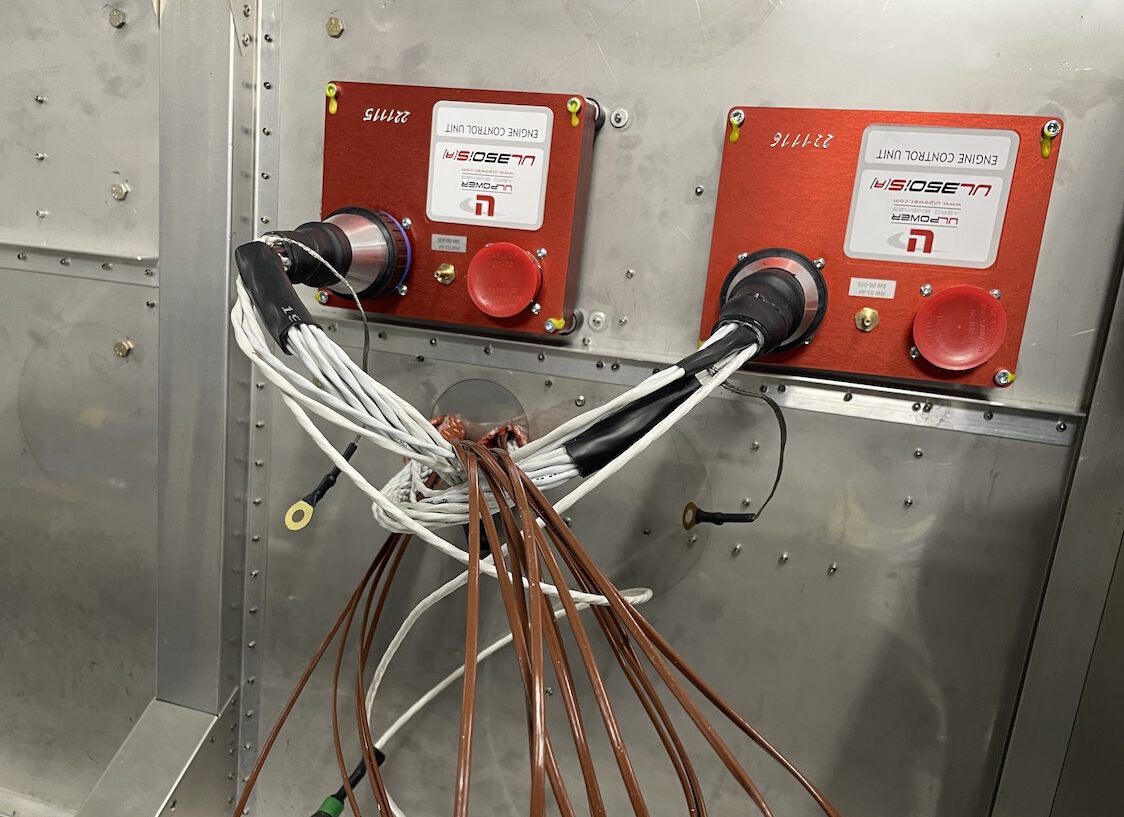 UL Power dual ECUs mounted to the aft side of the firewall on the passenger side.
Dynon Avionics Installation
Dynon Avionics will be providing instrumentation for this prototype, as they have for our tricycle gear Sonex-B prototype, and we’re excited to work with them to utilize their new tray mount system, which promises to simplify the installation process greatly. We have also determined that Dynon’s 10-inch HDX display will fit in the Highwing instrument panel. Dynon representative and Sonex builder David Weber will be visiting our facility later this month to help finalize the installation design process.
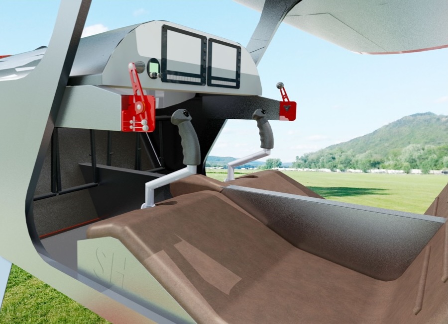
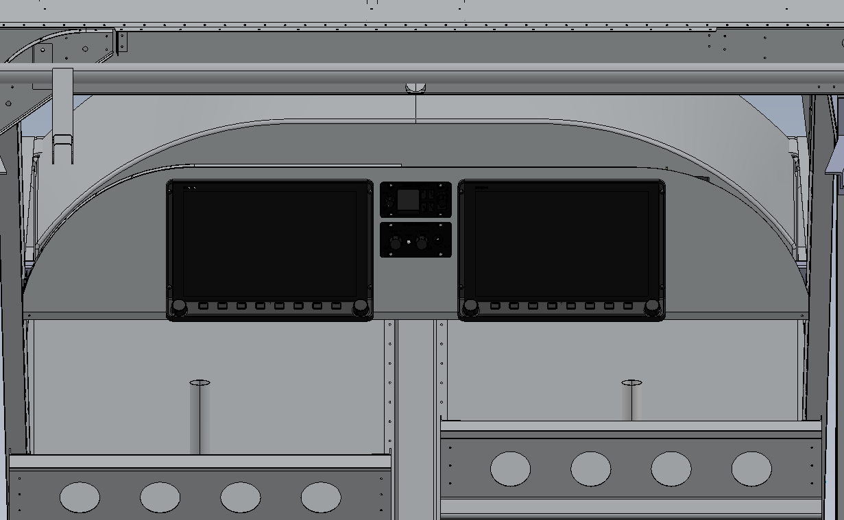 Sonex Highwing instrument panel with 10″ Dynon HDX displays (view from behind seats and rear wing spar center section).
 New Dynon mounting trays promise to simplify installation of the various system components while providing improved maintenance access.
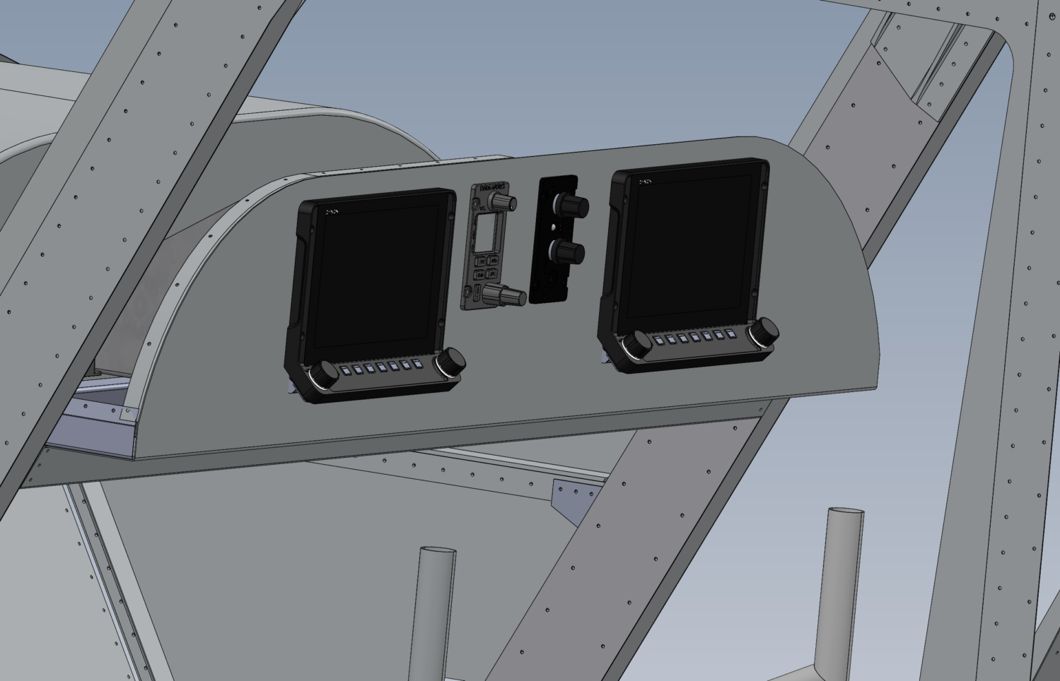 Panel layout with 7″ Dynon HDX displays.
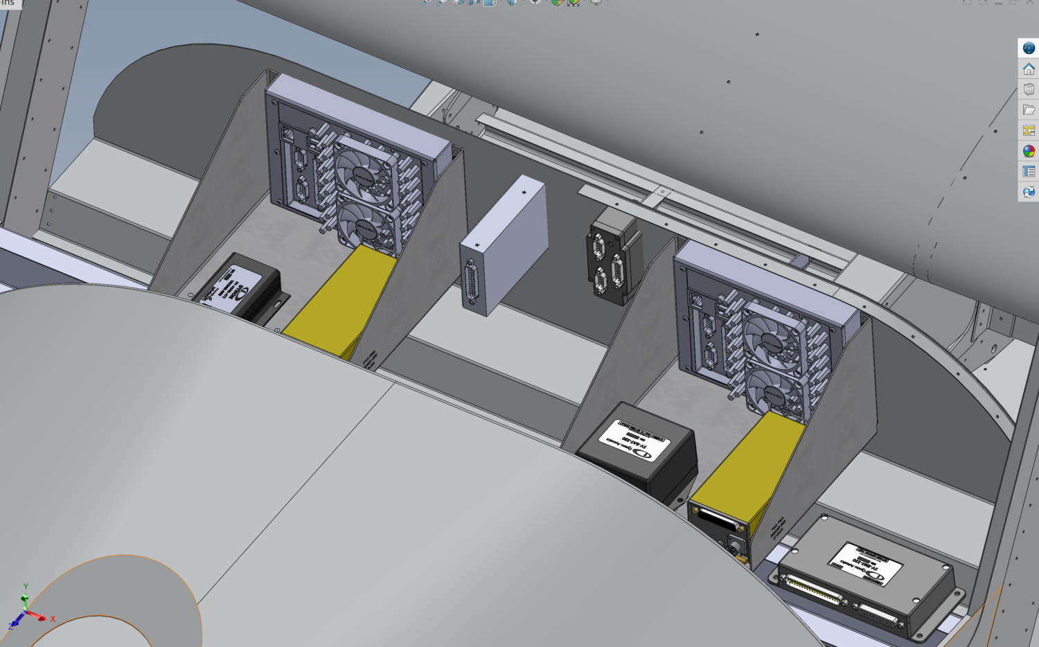 Mounting tray installation with 7″ Dynon HDX displays.
|
|
Sonex Highwing Estimated SpecificationsSubject to change without notice
* Sonex Highwing features easily interchangeable wing tips for different span configurations. Sonex Highwing is designed to take advantage of the new FAA MOSAIC rules for Light Sport Aircraft! Specifications & Performance Subject to Change Without Notice. |
||||||||||||||||||||||||||||||||||||||||||||||||||||||||||||||||||||||||||||||||||||||||||||||||
Sonex Aircraft Models
- Sonex Highwing
- Sonex-B
- Waiex-B
- Xenos-B Motorglider
- Onex
- SubSonex Personal Jet
- Sonerai Sport Aircraft